What the Heck Is Your PCB Vendor Talking About? – Common Terms for PCB Assembly
If you’ve ever tried to communicate with a PCB vendor and felt like they were speaking another language, you’re not alone. Like every specialized industry, printed circuit board manufacturing comes with its own vocabulary—shorthand that makes sense to engineers but may leave product developers, entrepreneurs, or first-time buyers completely lost. When you’re working on a new device, prototype, or full production run, clear communication is essential.
To help you feel confident when speaking with your PCB vendor, we’ve put together a simple, no-nonsense guide to the most common terms used in the printed circuit board industry. Whether you’re ordering a handful of prototypes or preparing for large-scale manufacturing, understanding these basics will save time, reduce confusion, and ensure you get exactly what you need.
For more details on PCB assembly services, visit:
https://yic-assm.com/printed-circuit-board-assembly-service/
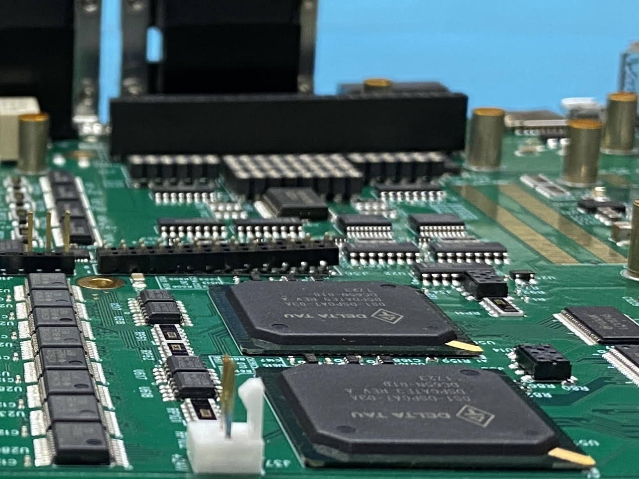
PCB – Printed Circuit Board
A PCB is the foundation of any electronic device. It is the physical board that electrically connects and supports components, acting like the “highway system” for signals and data. If a device computes, stores information, or communicates, it has a PCB inside.
THM – Through-Hole Mounting
Through-Hole Mounting is a traditional assembly method in which holes are drilled through the substrate, and components are inserted and soldered manually or by wave soldering. THM offers durability and strong mechanical bonding, making it ideal for connectors, large components, and devices exposed to vibration. Although largely replaced by SMT, THM is still important in certain industries.
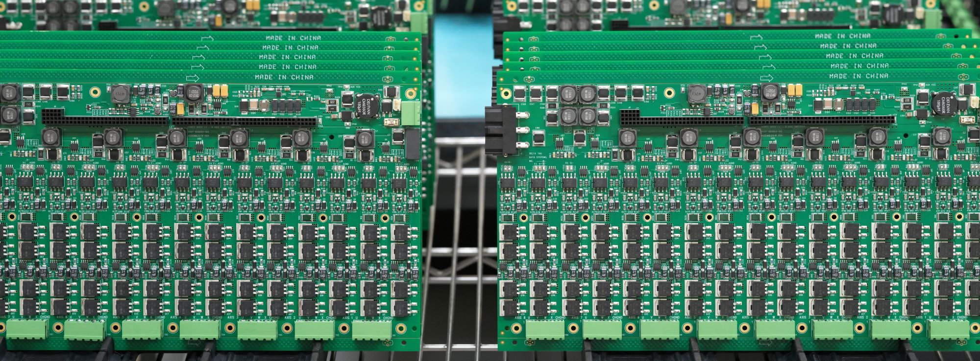
SMT – Surface Mount Technology
SMT revolutionized PCB assembly beginning in the 1960s and became the dominant method by the 1980s. SMT components sit directly on the surface of the PCB, eliminating the need for drilled holes. They are smaller, lighter, and allow components to be mounted on both sides of the board. This leads to higher component density, improved performance, and more compact electronics—qualities essential to modern designs.
Substrate
The substrate is the board material itself—the rigid or flexible base that supports all the conductive layers and components. Substrates must be non-conductive to prevent short circuits. Common substrate types include:
FR-4 (fiberglass-epoxy laminate) – the industry standard
Teflon – used for high-frequency applications
Ceramics – ideal for high-temperature environments
Specialty polymers – used in flexible and high-performance PCBs
Traces
Traces are the copper pathways that carry signals between components, similar to electrical wiring. Single-sided PCBs have copper only on one side; double-sided or multilayer PCBs distribute traces across several layers to support more complex circuits.
Soldermask
The familiar green coating on most PCBs is the soldermask. It insulates the copper traces, prevents accidental bridging during soldering, and protects the board from oxidation. While green is standard, PCBs can also be produced in red, blue, black, white, and other colors.
Understanding these key terms will help you communicate more effectively with your PCB assembly team and make informed decisions about your project. When you’re ready to move forward, Yun Industrial ACME PCB Assembly can help you with prototypes, small-batch production, and turnkey PCB assembly solutions:
https://yic-assm.com/printed-circuit-board-assembly-service/